An OEM request for “high flow” and a “tailored filter” sounds specific until an engineering team asks for allowable pressure drop, available space, exhaust temperature, and soot output. Without those numbers, several designs could satisfy the wording while behaving differently on the engine. The task is to translate broad purchasing terms into limits that can guide component design and acceptance testing.
A catalytic converter high flow specification concerns the converter’s resistance and conversion performance across operating points. A custom dpf specification concerns particulate capture, pressure rise as soot accumulates, regeneration, and packaging.
Their parameters interact, but each requirement must remain testable on its own. That distinction keeps an OEM project from treating two adjustable components as one vague solution.
Turn Requests into Measurable Boundaries
The initial engineering record captures the exhaust mass-flow and temperature ranges, target pollutants, expected soot production, maximum system backpressure, and installation dimensions.
Operating patterns belong in the same record, including prolonged low load or repeated starts, because they affect light-off and passive regeneration opportunities. These inputs allow a supplier to propose geometry and coating choices against a defined duty.
The system pressure budget needs a time dimension. A clean custom dpf may leave ample margin, whereas a loaded filter can move the system close to its limit before regeneration. Measurements at multiple soot states therefore matter more than a single initial pressure value. If the allowable limit is reached too early, the design may need another filter size, channel arrangement, or regeneration strategy.
An OEM team can then assign component-level targets without losing sight of the combined assembly. The catalytic converter high flow requirement, conversion, DPF capture and loading, thermal behavior, and mechanical fit become separate acceptance items. The relationships between them are documented so a proposed change in one device prompts review of the other.
The OEM specification distinguishes fixed interfaces from design freedoms. A fixed flange, for example, may constrain the shell, while coating and cell density remain adjustable within documented engine and emissions limits.
Configure the Converter for the Engine
Metal honeycomb substrates offer a low-restriction path and rapid heat transfer, while coating, length, diameter, shape, and cell density remain design variables. Diameter, length, shape, cell density, and coating are customizable in Hualian Catalyst‘s metallic converters; stated design priorities include fast light-off and mechanical strength.
A proposed catalytic converter high flow configuration should still be tested at the specified flow and temperature points; a geometry change can alter both pressure and conversion.
Mounting details and shell dimensions also matter in an OEM project. The converter must fit the exhaust system without creating unsupported loads or an unsuitable thermal interface. A coating that meets a bench conversion target may require re-evaluation if substrate length or cell density changes to solve packaging. Every design revision needs an updated measurement basis before equivalence can be claimed.
The converter’s output forms part of the filter’s inlet environment. Gas temperature and composition can influence regeneration conditions, while the converter’s pressure drop consumes part of the common resistance budget. Those effects are measured at the boundary between components rather than inferred from a “high flow” label.
A converter proposal should be accompanied by a pressure curve and conversion results for the actual substrate and coating. If dimensions change during packaging work, those measurements may no longer represent the ordered design. Linking each result to a drawing revision prevents an apparently small mechanical edit from silently changing the performance basis of the OEM project.
Specify the Filter as a Distinct Component
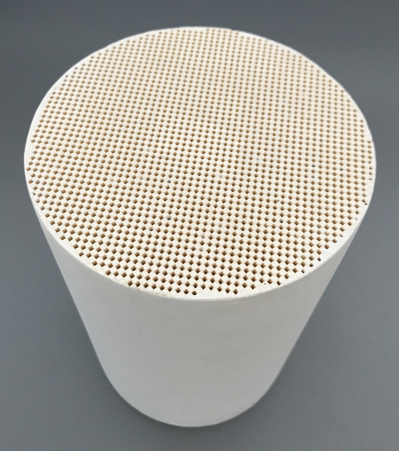
A custom dpf can be tailored in diameter, length, shape, and 100–350 CPSI cell density within Hualian’s listed DPF options. Its wall-flow channels capture soot, and both passive and active regeneration are supported.
Choosing among those options requires the engine’s flow, soot loading, temperature, and installation limits. A shape that fits the chassis may still require a different active area or length to meet pressure and capacity targets.
Regeneration is part of the filter requirement, not an afterthought. Passive operation depends on sufficiently favorable exhaust conditions; active operation provides added heat when needed. The acceptance plan should record the state at which regeneration starts, the resulting pressure change, and any relevant thermal limits. Test conditions need to reflect the proposed engine duty rather than an unrelated reference cycle.
The filter drawing must also distinguish the external package from the internal filtering specification. Diameter and length describe the envelope, but material, wall-flow geometry, and CPSI govern how the unit behaves under soot load. Acceptance criteria should connect those features to measured capture and pressure, so a filter that fits the available space is not automatically treated as complete.
The completed OEM specification can bring both component drawings and system measurements into one controlled record. It identifies fixed interfaces, permitted customization, test methods, and the revision used for each result.
A converter and filter meet the project only when the installed combination achieves the agreed emissions and pressure targets through the intended operating range. Converter flow gains disappear when a loaded filter pushes system pressure beyond engine limits.
